Document Control
| Document Number | HLX-CTMP-SCR-001 |
|---|---|
| Revision | 5.3 |
| Date | 18 April 2026 |
| Status | Preliminary Screening / For Decision |
| Prepared by | CTMP Programme Office |
| Reviewed by | CTMP Programme Office |
| Approved by | CTMP Programme Office |
| Distribution | Restricted — Internal Programme Use |
| Circulation Purpose | Internal technical screening and structured specialist review only |
| Scope | Corridor-level preliminary screening only |
| Decision Requested | Authorise bounded Phase 1 verification programme (post-activation) |
| Key Exclusions | No construction, procurement, land commitment, final site selection, or third-party solicitation |
Revision History
| Rev | Date | Author | Description |
|---|---|---|---|
| 1.0 | 15 Apr 2026 | CTMP Programme Office | Initial corridor screening |
| 2.0 | 16 Apr 2026 | CTMP Programme Office | Karst threshold unified; evidentiary claims recalibrated; weighted scoring matrix; phasing locked |
| 3.0 | 17 Apr 2026 | CTMP Programme Office | Decision memorandum; stage gates; assumptions register; scoring rubric; threshold rationale; verification programme table; document control; independent review note |
| 4.0-4.1 | 18 Apr 2026 | CTMP Programme Office | GIS exhibit and longitudinal profile; kill criteria split (screening threshold vs design basis status); weight rationale; What This Document Does Not Prove; Wall activation condition; satellite-referenced schematic with explicit exclusion buffers |
| 5.0 | 18 Apr 2026 | CTMP Programme Office | Rock/subsurface hazards desk study, bathymetry desk study, and coastal siting study integrated; audience and circulation locked; Ramsar naming convention clarified; language tightened throughout; Wall condition moved to Programme Gating Appendix; profile updated with Carton et al. (2009) reference and canyon hazard note; source/date notes added under figures |
| 5.1 | 18 Apr 2026 | CTMP Programme Office | Corridor selection basis stated; seismic return-period corrected to 475-year throughout; bathymetry claim in Annex B softened; Annex D failure triggers reframed as evaluation findings; slope instability reclassified as field-documented site hazard in Annex G |
| 5.2 | 18 Apr 2026 | CTMP Programme Office | Section 5 seismic qualifier aligned to 475-year return, rock site; Table 2 slope instability classification aligned to Annex G field-documented site hazard |
| 5.3 | 19 Apr 2026 | CTMP Programme Office | Table of Contents added; port expansion requirement and multi-vertical dependency statement added to Section 1 |
Table of Contents
Front Matter
Document Control and Revision History
Decision Memorandum
Naming Convention Note
Definitions and Abbreviations
Main Body
Executive Summary
1. Corridor Bathymetry and Access
1.1 Weighted Corridor Screening Matrix
2. Rock, Karst, and Geotechnical Hazards
3. Offshore Construction Feasibility
4. Scale and Phased Deployment
5. Seismic and Tsunami Hazards
6. Kill Criteria
7. What This Document Does Not Prove
8. Independent Review
9. Verification Programme
10. Stage Gates and Authority to Proceed
11. Conclusions
Annexes
Annex A: Screening Constraint Schematic
A.1 Corridor Longitudinal Profile
Annex B: Claim–Evidence–Reliability Register
Annex C: Required Verification Package
Annex D: Verification Programme Decision-Output Table
Annex E: Assumptions and Closure Register
Annex F: Corridor Screening Scoring Rubric
Annex G: Basis of Preliminary Screening Thresholds
Annex H: Failure Modes Summary
Appendices
Appendix J: Programme Gating Conditions
Sources
Decision Memorandum
This document is intended for internal technical screening and structured specialist review only. It is not a public-facing siting claim, feasibility study, or investment document.
Decision sought:
Authorise a bounded Phase 1 verification programme for the Chekka–Ras ash-Shaq’a corridor, limited to bathymetry, sub-bottom profiling, geotechnical investigation, karst testing, seismic/tsunami hazard definition, slope hazard assessment, and spatial constraint verification. No authorisation is sought for construction, procurement, land commitment, or final site selection.
Activation condition:
All verification work is contingent on programme activation conditions defined in Appendix J (Programme Gating Conditions). No work described in this document is initiated until those conditions are met.
Why this corridor is being advanced:
Under the weighted screening matrix (Section 1.1), the corridor scores highest among four evaluated candidates (6.85/10), driven by steep nearshore bathymetry (9/10) and existing heavy-industrial port access (9/10). This is a screening prioritisation result based on currently available evidence, not a feasibility conclusion. Other corridors have not been formally excluded and the matrix is subject to revision as new data emerges.
Why it is not yet endorsed:
The corridor carries unresolved geotechnical, hazard, and spatial-constraint risks that require field verification. These include: pervasive karst with active submarine spring discharge and seawater intrusion behaviour; documented slope instability (2018-2019 rockfall/landslide events rated "critical" by expert assessment); an active offshore thrust fault (Mount Lebanon thrust) within approximately 8 km of coast with documented seabed deformation; unquantified site-specific seismic and tsunami hazard; and unconfirmed spatial relationship to the adjacent Ras Chekka Ramsar site. Four key assumptions (A3, A4, A5, A6) remain at Low to Moderate confidence.
Module vs. corridor rejection:
A module-level failure does not by itself reject the corridor unless all viable alignments or prospective modules fail the governing thresholds. The corridor is rejected only if no module can satisfy all kill criteria.
What is explicitly not authorised:
Construction of any kind. Procurement of major equipment. Land acquisition or commitment. Final site selection. Disclosure of proprietary design parameters. Commitment to subsequent modules beyond verification of the first module corridor. Any solicitation of, or request to, any government, institution, or third party.
Next gate:
Gate 1 (spatial corridor confirmation via KML/GIS overlay), activated only after programme gating conditions are met (see Appendix J).
Naming Convention Note
This document uses two transliterations that refer to the same coastal headland. "Ras ash-Shaq’a" is used in the corridor designation (Chekka–Ras ash-Shaq’a corridor). "Ras Chekka" is used exclusively when referring to the Ramsar-listed protected area (site #3448, officially "Deir el Nouriyeh cliffs of Ras Chekka"). This is intentional, not inconsistent: one is a corridor engineering label, the other is the official protected-area designation recorded in the Ramsar Sites Information Service.
Definitions and Abbreviations
| Term | Definition |
|---|---|
| CTMP | Canal and Transshipment Mega Project |
| HLX Inc. | Hutchison Lea ConneXions Inc., programme sponsor |
| The Wall | Global citizen signature and public count at peoplesctmp.org establishing per-country deployment activation thresholds |
| Ras Chekka | Official designation of the Ramsar-listed protected area (site #3448, "Deir el Nouriyeh cliffs of Ras Chekka"). This is the protected-area name and is distinct from the corridor name. |
| Ras ash-Shaq’a | The coastal headland and geographic feature used in the corridor designation "Chekka–Ras ash-Shaq’a." Both transliterations refer to the same headland; this document uses Ras ash-Shaq’a for the corridor and Ras Chekka for the Ramsar site. |
| MLT | Mount Lebanon Thrust, a ~150 km offshore active thrust fault |
| Chekka Formation | Senonian chalk/marly chalk sequence with chert bands, up to ~500 m thick at Chekka |
| Kill criterion | Quantified screening threshold triggering abandonment or redesign. Not a final design limit. |
| Module | Self-contained deployment unit of approximately 50 GW |
| Screening threshold | Preliminary value for corridor prioritisation only; not a final design limit |
| Design basis | Validated, site-specific parameter established through field investigation |
| FS / PGA / PSHA | Factor of Safety / Peak Ground Acceleration / Probabilistic Seismic Hazard Analysis |
| TBM / HDD | Tunnel Boring Machine / Horizontal Directional Drilling |
| HVDC / ESIA | High Voltage DC transmission / Environmental and Social Impact Assessment |
| RQD | Rock Quality Designation, a core-logging measure of rock-mass quality |
| SHALIMAR | 2003 marine geophysical survey campaign offshore Lebanon (multibeam + seismic reflection) |
Executive Summary
This document addresses a single screening question: does the Chekka–Ras ash-Shaq’a coastal corridor warrant further investigation as a candidate site for subsurface hydro module deployment?
Based on publicly available data, project memoranda, and supporting desk studies (rock/subsurface hazards, bathymetry analysis, and coastal siting assessment), the corridor scores highest among four evaluated candidates under the weighted screening framework (6.85/10). This result reflects screening prioritisation based on currently available evidence; it is not a feasibility verdict.
The corridor carries unresolved geotechnical, hazard, and spatial-constraint risks that require field verification. Published geology describes the onshore rock mass as a mechanically heterogeneous stack of karstified Miocene limestone and weaker Senonian chalk/marl (the Chekka Formation, up to approximately 500 m thick), with documented active coastal karst featuring submarine spring outlets and seasonal seawater intrusion. Slope stability around the Ras Chekka headland has been assessed as "critical" following 2018-2019 rockfall and landslide events. Offshore, the Mount Lebanon thrust, an active approximately 150 km-long east-dipping thrust, is documented within approximately 8 km of the coast with fresh seabed deformation features. The nearshore shelf is characterised as extremely narrow, with published marine geophysics (SHALIMAR cruise, Carton et al. 2009) reporting depth increases from approximately 100 m to 1,500 m within less than 5 km in the central Lebanon margin, and canyon incision is common along the shelf.
The corridor is being screened for a programme concept ultimately targeting approximately 300 GW in phased modules. The present document supports only verification of a first module corridor and does not validate full programme deployment. The corridor is classified as prioritised for bounded verification pending field confirmation.
Scope limitation: This is a preliminary engineering screening based on available data and desk-study synthesis. It does not provide the physical deployment envelope, construction staging, hydraulic architecture, or export integration analysis required for institutional endorsement. Those elements require the verification programme defined in Section 8.
1. Corridor Bathymetry and Access
The Chekka–Ras ash-Shaq’a corridor lies within the central Lebanon margin sector characterised by Carton et al. (2009) as having an extremely narrow shelf and the steepest margin gradients along the Lebanese coast, with water depth increasing from approximately 100 m to 1,500 m in less than 5 km offshore. The LPA SEA baseline confirms the shelf does not extend beyond approximately 3 km between Enfeh and Ras Beirut. This steep nearshore gradient is the primary physical attribute that distinguishes the corridor: it provides qualitative alignment with the requirement for deep-water access within a constrained offshore distance.
The Chekka cement plant and its private port provide existing heavy-access infrastructure; however, if these facilities are utilised for the programme, they would require substantial expansion beyond their current capacity. The scope and nature of that expansion cannot be defined by this screening assessment alone, as it depends on a full analysis of all CTMP verticals (including but not limited to the Green Molecules Platform, desalination, green steel, green concrete, and data centre operations), none of which are addressed in this corridor screening. Port and logistics capacity requirements will be determined during pre-feasibility once the full vertical integration plan is assessed. The coast road infrastructure around the Ras Chekka headland provides trunk-road logistics access, though portal and staging siting must avoid the documented active slope-failure domains (Section 2). The proposed intake location lies east of the Ras Chekka Ramsar site; the exact georeferenced alignment is unconfirmed pending receipt of the corridor KML file (Annex C, item 02). Spatial confirmation is the subject of Gate 1.
Offshore, the desk-study bathymetry analysis notes that canyon incision is common along the margin, and sediment thickness can vary strongly over short distances, from thin or absent on canyon flanks to locally thicker in shelf embayments. The seabed may transition from relatively thin mobile sediments to exposed rock, canyon-head scarps, or steeply dipping sediment packages. This variability is a first-order engineering constraint for outfall siting and must be resolved by corridor-specific multibeam, backscatter, and sub-bottom profiling at Gate 2.
1.1 Weighted Corridor Screening Matrix
Table 1 presents a formal weighted comparison of four candidate corridors. These four were selected by applying the LPA SEA shelf-geometry segmentation to Lebanon's 225 km coastline, screening out segments with no port access or with direct protected-area overlap, and retaining one representative corridor per distinct shelf-geometry sector (broad northern shelf, narrow central shelf with port, steep central shelf without port, and moderate southern shelf). They are not claimed to be exhaustive; additional candidates could be added to the matrix if a sector-specific screening identifies them. This matrix is a screening prioritisation tool only, intended to rank candidates for further investigation. It is not a feasibility assessment and does not constitute endorsement of any corridor. The scoring weights are a programme screening convention adopted for this prioritisation exercise, not a universal engineering standard. All scores are subject to revision following field verification.
Weight rationale:
Nearshore depth (30%) is the primary physical constraint: corridors that cannot provide deep-water access within the design distance band are non-viable regardless of other factors. Infrastructure access (25%) reflects the cost and schedule penalty of building port and road access from scratch. Geotechnical risk (20%) reflects the probability of corridor-invalidating subsurface conditions. Social constraints (15%) and environmental sensitivity (10%) receive lower weights because they are more amenable to design mitigation at screening stage, though either can still generate a kill condition.
Table 1: Weighted Corridor Screening Matrix
| Corridor | Depth (30%) | Infra (25%) | Geotech (20%) | Social (15%) | Env (10%) | Weighted |
|---|---|---|---|---|---|---|
| Chekka–Ras ash-Shaq’a | 9 | 9 | 4 | 5 | 6 | 6.85 |
| Akkar (North) | 4 | 4 | 6 | 7 | 7 | 5.15 |
| Beirut–Batroun | 9 | 8 | 5 | 3 | 4 | 6.30 |
| Tyre–Naqoura | 5 | 6 | 6 | 5 | 2 | 5.00 |
See Annex F for the complete scoring rubric.
2. Rock, Karst, and Geotechnical Hazards
The supporting rock and subsurface hazards desk study characterises the corridor’s onshore geology as a mechanically heterogeneous stack of two primary engineering units: (i) Miocene massive limestone, karstified and fractured, with potentially high intact strength but highly variable rock-mass quality due to jointing, dissolution cavities, and perched seepage; and (ii) Senonian chalk/marl with chert bands (the Chekka Formation, reported thickness approximately 100-500 m), with lower intact strength, time-dependent weakening when saturated, and a tendency to form preferential sliding horizons beneath stronger limestone caps.
The coastal karst system is not speculative. Modern hydrogeological syntheses (Fleury et al. 2023, Bakalowicz 2018) document submarine spring outlets at Chekka Bay discharging at approximately 23 m below sea level, with deeper outlets activating at approximately 110 m below sea level during winter floods. The system exhibits seawater intrusion during low-flow stages, demonstrating that karst conduits are hydraulically open to the sea at multiple depths. For underground works, this means the controlling hazard is pressurised, conduit-dominated inflow that can be saline or brackish depending on season and marine head conditions.
Slope stability around the Ras Chekka headland has been assessed as "critical" following documented 2018-2019 rockfall and landslide events. The expert field assessment describes rockfalls from overhanging limestone layers, earthflows/landslides in marls, and drainage dysfunction, all consistent with a rock mass where strength and permeability are discontinuity-controlled. Any portal or surface infrastructure siting must treat slope-structure interaction as a primary hazard.
In the absence of site-specific borehole data, the screening assumes adverse karst conditions for risk-ranking purposes. This assumption (A3) carries low confidence and is the single highest-priority item for the verification programme. A new assumption (A6) addresses the requirement to site portals outside documented active slope-failure domains. See Annex E for the full assumptions register.
Governing karst kill threshold: continuous void exceeding 50 m along any tunnel alignment triggers immediate module abandonment. This is an engineering-judgment provisional screening threshold (see Annex G) and is the single governing karst value throughout this document. It is not a final design limit.
3. Offshore Construction Feasibility
The bathymetry desk study confirms that the nearshore slope is steep, consistent with published marine geophysics, but cautions that the seabed may vary from thin mobile sediments to exposed rock, canyon-head scarps, or steeply dipping packages over short lateral distances. Offshore of the corridor, the Mount Lebanon thrust system has been demonstrated by SHALIMAR multibeam and seismic reflection data, with fresh seabed deformation features documented by Elias et al. (2007). This constitutes a desk-study red flag for placing critical marine infrastructure without corridor-specific verification.
We assume (A4) that at least one marine tunneling method will prove viable if geology permits, but this assumption carries low confidence absent site-specific sub-bottom profiles, rock-mass characterisation (including RQD and discontinuity mapping), and assessment of whether the host rock is dominantly karstified limestone (void risk) or chalk/marl (deformability risk).
Detailed internal geometry, hydraulic layout, and construction sequencing are outside the scope of this preliminary screening and will be disclosed only within the controlled verification and pre-feasibility workstream under appropriate confidentiality arrangements. Their omission is intentional and does not affect the limited decision sought by this document.
4. Scale and Phased Deployment
The corridor is being screened for a programme concept ultimately targeting approximately 300 GW in phased modules. The present document supports only verification of a first module corridor and does not validate full programme deployment.
The programme is structured as approximately six modules of roughly 50 GW each. For context, the world’s largest hydroelectric installations operate in the 15-22 GW range. The IEA notes the MENA region aims to add capacity on the order of 300 GW by 2030, but distributed across many projects.
5. Seismic and Tsunami Hazards
The supporting desk study identifies seismic hazard as a special case for coastal Lebanon. Published PSHA work reports mean PGA values of approximately 0.25-0.30 g for coastal cities (475-year return, rock site), with values exceeding 0.3 g along substantial portions of the coast between Saida and Tripoli, attributed in part to proximity to the Mount Lebanon thrust. The earthquake catalogue compilation stresses that the 20th century instrumental period is not representative of long-term destructive events.
The Mount Lebanon thrust is described as an active, approximately 150 km-long, east-dipping crustal thrust whose surface trace lies mainly offshore between Tripoli and Saida and cuts the seabed at approximately 8 km from the coast. For this corridor, the active fault question is not limited to distant inland strike-slip faults; there is a nearshore offshore thrust source that must be treated as a design-basis contributor to both strong motion and potential permanent seabed deformation.
Historical sources document the 551 AD earthquake (estimated Ms approximately 7.2) with tsunami and coastal landslides in the corridor region. Both hazards, strong shaking and slope failure, are coupled: seismic demand on tunnels/caverns combined with potential portal burial or blockage from triggered slope failures, plus nearshore seabed deformation affecting marine structures.
Kill criteria: ground motion exceeding 0.3 g (475-year return, rock site) invalidating structural design (FS < 1.5) kills the module. Tsunami inundation exceeding 5 m at intake elevation kills the module. Both are screening thresholds that will be superseded by site-specific PSHA and tsunami modelling at Gate 4 (see Annex G). The site-specific PSHA must explicitly include the offshore Mount Lebanon thrust as a source and account for the catalogue limitation that instrumental seismicity under-represents long-term destructive potential.
6. Kill Criteria
Table 2 defines kill thresholds with Screening Threshold and Design Basis Status presented side by side. No screening threshold should be interpreted as a final design limit. Design basis values will be established through the verification programme.
A module-level failure does not by itself reject the corridor unless all viable alignments or prospective modules fail the governing thresholds.
Table 2: Kill Criteria
| Failure Mode | Screening Threshold | Design Basis Status | Action |
|---|---|---|---|
| Karst voiding | Continuous void >50 m along any tunnel alignment. Governing threshold for all karst references. | Provisional (engineering judgment). To be validated by borehole programme at Gate 3. | Abandon affected module. Module failure does not reject corridor unless all alignments fail. |
| Excessive inflow | Water ingress exceeding pump capacity; unsealable fractures | Provisional. Pump capacity to be set during pre-feasibility. | Abandon affected module |
| Depth runout | Required trench/tunnel exceeds ±50% of design baseline | Provisional. To be refined by bathymetric survey at Gate 2. | Abandon affected module |
| Tunnel stability | Factor of safety FS < 1.5 in any section | Source-derived (international tunnel design codes). Expected stable. | Downsize or abandon module |
| Env. overlap | Intake/outfall encroaches on protected zone | Source-derived (Ramsar Convention, Lebanese environmental law). Binary. | Re-route or abort module |
| Seismic overload | Expected PGA > 0.3 g (475-year return, rock site) invalidating structural design | To be finalised. Site-specific PSHA at Gate 4 will supersede. | Abandon module |
| Tsunami inundation | Modeled wave > 5 m at shoreline intake elevation | To be finalised. Site-specific tsunami modelling at Gate 4 will supersede. | Abandon module |
| Slope instability | Portal or surface works within documented active failure domain | Field-documented site hazard (2018-2019 Ras Chekka failure documentation). To be refined by field mapping. | Relocate portal; abandon module if no viable alternative |
| Offshore thrust interaction | Alignment crosses mapped seabed fault scarp or active deformation zone | To be finalised. Corridor-specific multibeam at Gate 2 will define. | Re-route or abandon module |
| Cost overrun | Phase CAPEX > 2× baseline estimate | Provisional. Baseline to be developed during verification. | Cancel remaining phases |
See Annex G for rationale and provenance of each threshold.
7. What This Document Does Not Prove
This document does not prove that the corridor is feasible.
It proves only that the corridor scores highest under a preliminary weighted screening and therefore warrants bounded verification.
This document does not prove that subsurface conditions will support tunnel construction.
No borehole, sub-bottom profile, or site-specific geotechnical data exists. The rock mass is mechanically heterogeneous (karstified limestone over weak marls), with active coastal karst and documented slope instability. Assumptions A3 and A6 carry Low confidence.
This document does not prove that seismic or tsunami hazards are within designable limits.
An active offshore thrust fault has been documented within approximately 8 km, with fresh seabed deformation features. The instrumental seismicity record is acknowledged as not representative of long-term destructive events. Assumption A5 carries Moderate confidence.
This document does not prove that the corridor avoids all protected areas.
The georeferenced corridor polygon has not been overlaid against protected area boundaries. Avoidance is indicated but unconfirmed pending Gate 1.
This document does not prove that 300 GW can be deployed at this site.
It supports verification of a single first-module corridor only.
This document does not prove that the offshore seabed is competent.
Published sources describe canyon incision, variable sediment thickness, and seabed fault scarps along the margin. Foundation-grade seabed properties require corridor-specific survey.
This document does not request, solicit, or require anything from any party.
It is an internal engineering assessment. Programme activation conditions are defined separately in Appendix J.
8. Independent Review
This screening assessment should be independently reviewed by qualified specialists in: coastal and marine geotechnical engineering, rock mechanics and underground construction in karstic carbonate, sub-bottom and bathymetric survey interpretation, structural-seismic design including near-fault effects, probabilistic tsunami hazard assessment, slope stability and rockfall hazard assessment, and environmental/ecological constraint analysis. The document is not self-certifying.
9. Verification Programme
The following work would be required before this corridor could advance beyond preliminary screening. Each activity addresses a specific evidence gap and enables a specific stage-gate decision. See Annex D for the complete decision-output mapping.
The types of investigation required include, in general terms: spatial verification against protected area and settlement registers; high-resolution multibeam bathymetry with backscatter and sub-bottom profiling; geotechnical drilling with rock-mass characterisation across the full stratigraphic stack; karst-specific investigation including tracer tests, packer tests, and seasonal piezometry with salinity profiling; slope hazard assessment with LiDAR and rockfall modelling; and site-specific PSHA and tsunami modelling explicitly incorporating the offshore Mount Lebanon thrust source.
Timeline: A realistic verification programme of this nature would typically span 6-12 months from mobilisation, depending on survey scope and weather windows. The programme would include defined go/no-go decision gates after each major data delivery.
10. Stage Gates and Authority to Proceed
Each gate requires specific evidence before advancement. Failure at any gate halts advancement until the corridor is redefined or rejected. No gate may be bypassed. All gates are preceded by the overarching programme activation conditions defined in Appendix J.
Table 3: Stage-Gate Structure
| Gate | Milestone | Evidence Required | Fail Outcome |
|---|---|---|---|
| 0 | Desktop screening complete | This document accepted by programme authority | Corridor not advanced |
| 1 | Spatial corridor confirmed | KML/GIS overlay confirms no protected-area intrusion and viable land access | Corridor redefined or rejected |
| 2 | Geometric and seabed plausibility | Multibeam bathymetry, sub-bottom profiling, and backscatter confirm depth/runout within design band; canyon heads and seabed scarps mapped | Corridor rejected if runout exceeds kill criterion or seabed is non-viable |
| 3 | Geotechnical viability confirmed | Borehole, karst investigation, and rock-mass characterisation confirm at least one viable module alignment; groundwater/salinity regime bounded | Module alignment rejected; corridor rejected if all fail |
| 4 | Hazard envelope confirmed | Site-specific PSHA (including offshore Mount Lebanon thrust), tsunami modelling, and slope stability assessment confirm designable hazard levels | Corridor rejected if hazard exceeds kill criteria |
| 5 | Pre-feasibility authorised | Gates 1–4 passed; pre-feasibility scope, budget, and schedule approved for one module only | Programme paused |
11. Conclusions
Under the weighted screening framework, the Chekka–Ras ash-Shaq’a corridor scores highest among four evaluated candidates (6.85/10). This is a screening prioritisation result, not a feasibility conclusion. The site carries high geotechnical uncertainty (documented karst, slope instability, and rock-mass heterogeneity), an active nearshore offshore thrust fault with documented seabed deformation, and unconfirmed spatial relationship to the adjacent Ras Chekka Ramsar site.
This screening classifies the corridor as prioritised for bounded verification pending field confirmation. It justifies proceeding to the verification programme defined in Section 9, executed through the stage-gate structure in Section 10, contingent on programme activation conditions (Appendix J). It does not constitute a site conclusion, institutional endorsement, or request to any party.
Evidence integrity: This document distinguishes between High, Moderate, and Low reliability claims (Annex B). Assumptions A3, A4, A5, and A6 are the critical evidence gaps. The Assumptions and Closure Register (Annex E) defines the closure path for each.
Annex A: Screening Constraint Schematic
The following schematic presents the corridor polygon, Ramsar protected area boundary, settlement zones with explicit 1 km exclusion buffers, cement plant and port infrastructure, indicative offshore depth contours, and candidate offshore alignment. This is not a GIS export. All geometry is indicative, derived from satellite imagery and publicly available data. Spatial confirmation requires georeferenced KML/GIS overlay at Gate 1.
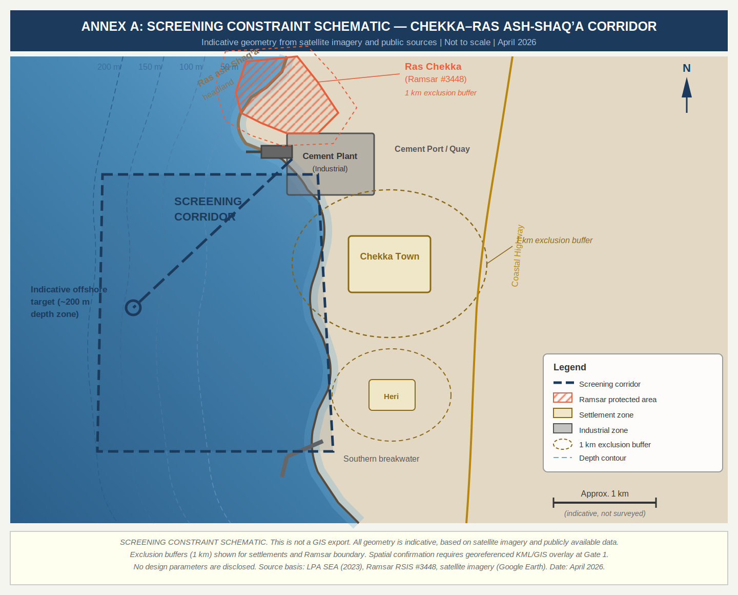
Source basis: satellite imagery, LPA SEA (2023), Ramsar RSIS #3448, publicly available mapping. Screening-grade only; not survey control. Date: April 2026.
A.1 Corridor Longitudinal Profile
The following profile shows the indicative seabed gradient from shore to target offshore depth, based on Carton et al. (2009) SHALIMAR cruise characterisation of the central Lebanon margin steep-slope sector. Canyon hazard and the screening target depth band are indicated.
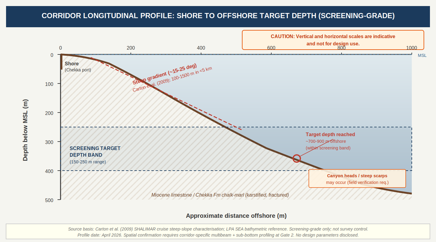
Source basis: Carton et al. (2009) steep-slope characterisation; LPA SEA bathymetric reference. Screening-grade only; not survey control. Vertical and horizontal scales are indicative and not for design use. Date: April 2026.
Annex B: Claim–Evidence–Reliability Register
| Claim | Evidence Source | Reliability |
|---|---|---|
| Chekka nearshore zone provides access to approximately 100-200 m depth within a few hundred metres, with much deeper water within a few kilometres | LPA SEA NTS (2023); Carton et al. (2009) SHALIMAR | High (primary bathymetric data) |
| Chekka geology is karstic limestone + marl/chalk | Fleury et al. (2023); slope hazard report; Dubertret mapping | High (peer-reviewed + field documentation) |
| Active offshore thrust within ~8 km of coast | Elias et al. (2007); Huijer et al. (2011); SHALIMAR multibeam | High (peer-reviewed marine geophysics) |
| Documented slope failures at Ras Chekka (2018-2019) | Expert slope-instability assessment report | High (field-based documentation) |
| Submarine karst springs with seawater intrusion | Fleury et al. (2023); Bakalowicz (2018) | High (peer-reviewed hydrogeology) |
| Canyon incision common along margin | Carton et al. (2009); RAC/SPA Deep Sea Lebanon | High (direct survey observation) |
| Adverse karst along tunnel alignment | Internal assumption (A3) | Low (pending borehole verification) |
| Marine tunneling method viable | Internal assumption (A4) | Low (no site-specific data) |
| Tsunami guidance applicable | Internal assumption (A5) | Moderate (regional analogy) |
| Portal siting outside failure domains | Internal assumption (A6) | Low-Moderate (pending field mapping) |
Annex C: Required Verification Package
| File | Type | Contents |
|---|---|---|
| 01_Interface_Requirements | Design specs, environmental limits, interface definitions | |
| 02_Corridor_KMZ | KMZ/KML | Georeferenced corridor polygon with coordinate system |
| 03_Seafloor_Survey | PDF+data | Multibeam bathymetry, backscatter, sub-bottom profiles |
| 04_Geotech_Boreholes | XLSX | Borehole/CPT logs, televiewer, RQD, core photographs |
| 05_Karst_Study | Karst drilling, dye-trace, packer tests, hydrogeological model | |
| 06_Seismic_Tsunami | Site-specific PSHA (incl. MLT), fault maps, tsunami modelling | |
| 07_Slope_Hazard | LiDAR survey, rockfall modelling, portal exclusion zones | |
| 08_Environmental_Baseline | Habitat mapping, stakeholder register, risk assessments | |
| 09_HVDC_Design | HVDC cabling, converter specs, grid intertie plan | |
| 10_TEAnalysis | XLSX | CAPEX/OPEX breakdown and financing assumptions |
| 11_Permitting_Plan | Regulatory roadmap with agencies and sequencing | |
| 12_Claims_Register | XLSX | Public claims and source register for audit |
Items 02 (Corridor KMZ), 05 (Karst Study), and 07 (Slope Hazard) are highest priority.
Annex D: Verification Programme Decision-Output Table
| Activity | Method | Key Output | Decision | Failure Trigger | Discipline |
|---|---|---|---|---|---|
| Spatial verification | KML/GIS overlay | Confirmed polygon with buffer compliance | Gate 1 | Protected area intrusion | GIS/Planning |
| Bathymetric survey | Multibeam + backscatter + sub-bottom | Depth/gradient model; canyon heads; seabed scarps; substrate classification | Gate 2 | Runout exceeds design band; evaluation of canyon-head proximity and scarp interaction for alignment viability | Marine Survey |
| Geotechnical investigation | Boreholes, CPT, core, televiewer, RQD | Rock quality, void distribution, strength/deformability across stratigraphic units | Gate 3 | Void >50 m; FS < 1.5; evaluation of marl-dominated sections for support feasibility | Geotech Eng. |
| Karst/hydrogeology | Dye-trace, packer tests, piezometry, salinity profiling | Karst connectivity model; seasonal groundwater/salinity regime | Gate 3 | Uncontrollable conduit inflow; saline intrusion incompatible with design | Hydrogeology |
| Slope hazard assessment | LiDAR, photogrammetry, engineering geomorphology, rockfall modelling | Active failure domain map; portal exclusion zones | Gate 3 | Evaluation confirms no viable portal location outside documented failure domains | Geotech Eng. |
| Seismic hazard | Site-specific PSHA with MLT source | Design basis PGA, response spectra | Gate 4 | PGA > 0.3 g invalidating FS 1.5 | Seismology |
| Tsunami hazard | Numerical inundation modelling | Wave height at intake elevation | Gate 4 | Wave > 5 m at intake | Coastal Haz. |
Annex E: Assumptions and Closure Register
| ID | Assumption | Why It Exists | If False | Closure Data | Owner | Gate |
|---|---|---|---|---|---|---|
| A3 | Adverse karst conditions along alignment | No borehole data; Fleury et al. and Bakalowicz confirm active coastal karst with submarine outlets and seawater intrusion | If less severe, risk improves; if worse, module abandoned | Coring, optical/acoustic televiewer, packer tests, tracer tests | Geotech Lead | Gate 3 |
| A4 | At least one marine tunneling method viable if geology permits | No sub-bottom profile or constructability study; rock-mass heterogeneity (limestone vs weak marls) confirmed by desk study | Module cannot be constructed; corridor may be rejected | Sub-bottom profiles, rock classification, RQD, TBM/HDD feasibility | Marine Eng. | Gate 3 |
| A5 | Regional tsunami guidance applicable | No site-specific PTHA; offshore Mount Lebanon thrust documented as tsunamigenic source; 551 AD event documented | Intake invalidated if wave exceeds screening threshold | Site-specific PSHA and tsunami modelling including MLT source | Seismic Lead | Gate 4 |
| A6 | Portal siting outside active slope-failure domains is achievable | 2018-2019 Ras Chekka failures documented; expert assessment rates slope condition as critical | Portal burial, blockage, or damage; module abandoned if no alternative access | Engineering geomorphology mapping, LiDAR, rockfall modelling | Geotech Lead | Gate 3 |
Annex F: Corridor Screening Scoring Rubric
This rubric defines the criteria, weights, and score bands for the weighted matrix. The matrix is a screening prioritisation tool only, not a feasibility assessment. The scoring weights are a programme screening convention adopted for this exercise, not a universal engineering standard.
| Criterion | Weight | Score 8–10 | Score 4–7 | Score 1–3 |
|---|---|---|---|---|
| Nearshore Depth | 30% | Target depth within <0.5 km, confirmed by bathymetric source | Target depth within 0.5–1.5 km, or data resolution insufficient | Target depth >1.5 km or data absent |
| Infrastructure | 25% | Heavy-lift port within corridor, road access for oversize loads, industrial land | Port within 10 km requiring upgrade, or road constrained | No port; greenfield build |
| Geotechnical Risk | 20% | Competent rock, no significant karst per published data | Moderate complexity; karst present but potentially manageable | Severe karst, deep weathering, documented slope failures |
| Social | 15% | Industrial zone; no displacement; buffer >1 km | Adjacent settlement but no displacement required | Requires displacement or dense urban area |
| Environmental | 10% | No protected areas in corridor or buffer | Protected area adjacent but avoidance achievable | Protected area overlap confirmed or highly probable |
Annex G: Basis of Preliminary Screening Thresholds
Four classifications are used: Source-derived (published codes/standards, expected stable). Engineering-judgment provisional (professional judgment, must be validated). To be finalised after verification (regional data by analogy, will be superseded). Field-documented site hazard (threshold derives from direct observation of site conditions rather than design codes; expected stable unless site conditions change). No screening threshold is a final design limit.
| Threshold | Screening Value | Classification | Basis |
|---|---|---|---|
| Karst void extent | >50 m continuous | Engineering-judgment provisional | Tunnel boring experience in comparable carbonate formations. To be validated at Gate 3. |
| Tunnel FS | FS < 1.5 | Source-derived | International tunnel design codes for seismically active regions. |
| Seismic PGA | >0.3 g (475-yr) | To be finalised | Upper bound of regional PSHA (Huijer et al.; Rahhal and Yassine). Site-specific PSHA at Gate 4 will supersede. |
| Tsunami wave | >5 m at intake | To be finalised | Historical catalogue including 551 AD event. Site-specific modelling at Gate 4. |
| Depth runout | >±50% design | Engineering-judgment provisional | Viable construction range at screening level. Carton et al. (2009) steep-slope data supports. Gate 2. |
| Slope instability | Active failure domain | Field-documented site hazard | 2018-2019 Ras Chekka failure documentation and expert assessment. Classification reflects direct field observation, not design-code derivation. |
| Offshore thrust | Mapped seabed scarp | To be finalised | Elias et al. (2007) document fresh seabed breaks; MLT within ~8 km. Gate 2 multibeam. |
| Cost overrun | >2× baseline | Engineering-judgment provisional | Standard contingency for pre-feasibility screening. |
Annex H: Failure Modes Summary
See Table 2 (Section 6) for governing kill criteria with screening threshold and design basis status. The karst voiding threshold of 50 m continuous void is the single governing value. A module-level failure does not by itself reject the corridor unless all viable alignments fail. See Annex G for provenance.
Appendix J: Programme Gating Conditions
This appendix defines the programme-level activation conditions that precede all technical stage gates in this document. It is separated from the engineering body to maintain clarity of audience: the engineering sections address technical screening; this appendix addresses programme governance.
Activation condition:
The verification programme described in this document is contingent on Lebanon reaching the CTMP deployment activation threshold: a minimum of 5% of the national population recorded as signatories on The Wall (peoplesctmp.org). Until this threshold is met, no verification work is initiated, no resources are committed, and no engagement with local or national authorities is undertaken.
Rationale:
The CTMP deployment sequence is people-determined. The Wall threshold is the mechanism by which citizen demand is established as the precondition for programme advancement in any country. This is a foundational programme principle, not a contingency or a negotiating position. Technical screening proceeds in parallel with The Wall campaign to ensure that when the activation threshold is reached, the engineering assessment is ready and the verification programme can be mobilised without delay.
Current status:
As of the date of this document, Lebanon has not reached the 5% activation threshold. This document is therefore a preparatory engineering assessment. No action described herein is authorised for execution until activation conditions are met.
Sources
Lebanese Petroleum Administration (2023). Offshore Lebanon Strategic Environmental Assessment, Non-Technical Summary.
Fleury, P., Pistre, S., & Bakalowicz, M. (2023). Coastal karst aquifers and submarine springs in Lebanon. Comptes Rendus Geoscience.
Bakalowicz, M. (2018). Coastal karst groundwater in the Mediterranean. Environmental Earth Sciences.
Carton, H. et al. (2009). Seismic evidence for Neogene and active shortening offshore of Lebanon (Shalimar cruise). Journal of Geophysical Research.
Elias, A. et al. (2007). Active thrusting offshore Mount Lebanon. Geology.
Huijer, C. et al. (2011). Probabilistic seismic hazard assessment of Lebanon. Lebanese Science Journal.
Rahhal, M. & Yassine, R. (2020). Fault-based probabilistic seismic hazard analysis of Lebanon. Bulletin of Earthquake Engineering.
RAC/SPA (2017). Deep Sea Lebanon scientific report (OCEANA survey).
World Bank (2019). Lebanon Electricity Transmission Project (P170769), Project Information Document.
International Energy Agency (2023). The Future of Electricity in the Middle East and North Africa.
U.S. Department of Energy (2022). Connecting the Country with High Voltage DC.
Ramsar Convention Secretariat (2019). RSIS #3448, Deir el Nouriyeh (Ras Chekka).
Lebanon Ministry of Environment. Tyre Coast Protected Area.
NCESSA (2019). Lebanon Environmental Legislation at Project Level.